


TARGET Solar
BLOGS CENTER
Release Time: Apr 23,2025
LB56-500kW WTGS

The wind rotor is used to convert the kinetic energy of the air into the mechanical energy ofwind rotor. The wind turbine adopts a three-blade, upwind type which is actively adjusted throughpitch mechanism. The blade material uses reinforced fiber glass.
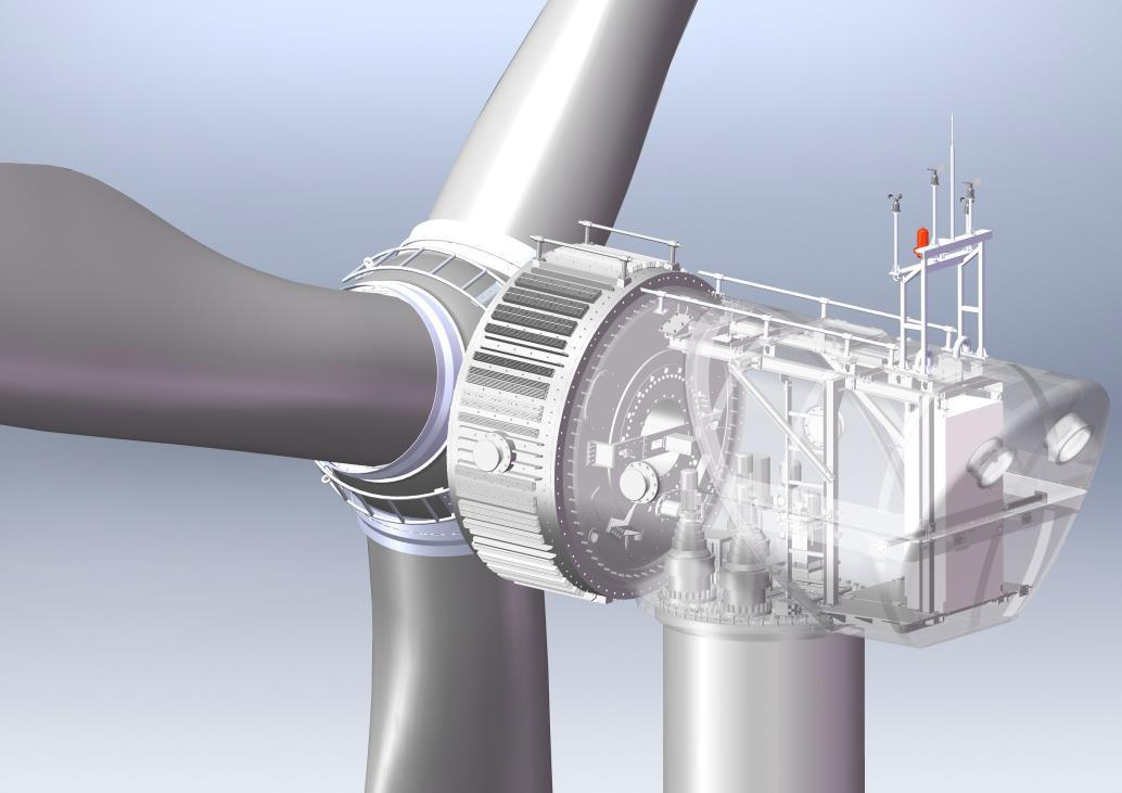
Nacelle
The nacelle is connected to generator and tower, which contains yawing transmission system.damper control system, wind turbine control system, sensors, wind measurement system, aviationwarning system, staff passage, etc., as shown in the figure,
Three-blade independent pitch mechanism
Pitch of WTG adjusts the windward angle of blades, and its main functions are poweradjustment and rotation speed control. it mainly includes hub, pitch reducer, drive motor, pitchcontroller, angle speed detection device, etc. The hub adopts a spherical structure, which hasgood castability and high strength, as shown in the left picture below:
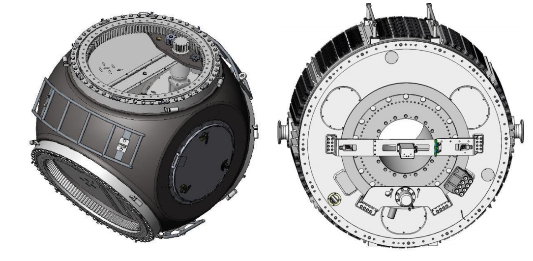
Generator & braking system
The generator converts the mechanical kinetic energy of wind rotor into electrical energy. itis composed of stator, rotor, brake disc, braking system and detection device. The main shaft ofWTG is braked to realize blade braking, which is composed of brake disc and hydraulic brakingsystem, as shown on the right above. As shown in the figure.
Yawing system
Wind turbine adopts active yawing to direct wind and consists of three yaws drive devices.yaw angle detection device, twisting detection device and hydraulic brake. Yaw braking isaccomplished by yaw reduction motor, which uses an electromagnetic brake.
Lubrication system
The lubrication system of WTG consists of automatic lubrication and manual lubrication. Theyaw pivotal bearing and the front and rear main shaft lubrication of the generator are independentautomatic lubrication systems. The three independent pitch bearings are independent lubricationsystems and each bearing position is equipped with waste oil collection bottle.
Tower
Tower mainly plays the role of supporting nacelle, generator and wind rotor. it consists oftower itself, ladder, lighting and ladder safety protection devices. Each floor of tower is equippedwith a platform for installation and rest, etc.

2.Technical parameter
Wind turbine generator system parameter
| Manufacturer | Xiamen Lianbang Technology Co.,Ltd |
| Country of origin | China |
| Parameter | Specs |
| System model | LBGP56-500、LBGP56-400 |
| Device model | LB56-500、LB56-400 |
| Design standard | IEC61400-1、NBT 31107-2017 WTGS with low wind speed |
| Design class | IEC S(DIIA) |
| Type | Permanent magnet direct drive,three blades,horizontal axis,upwind |
| Design lifespan | 20 years |
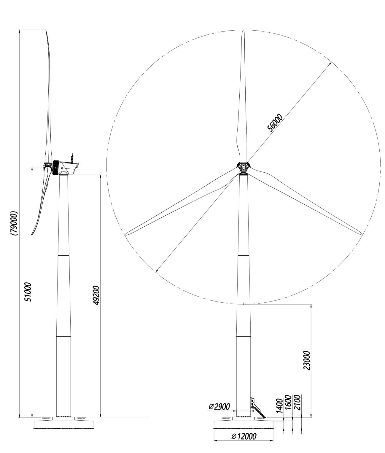
| Rotor diameter | 56m |
| Hub height | approximately 51m |
| Tower type | Tubular column |
| Performance | |
| Power regulation | Individual pitch control |
| Rated power | 500kW、400kW |
| Swept area | 4.92 m2/kw、6.15 m2/kW |
| Rated rotation speed | 29rpm、28rpm |
| Max rotation speed | 33rpm |
| Cut-in wind speed | 3m/s |
| Rated wind speed | 10.5m/s、9.5m/s |
| Cut-out wind speed | 18m/s(10min),22m/s(10s) |
| Survival wind speed | 52.5m/s |
Wind turbine component parameter
| Weight | |
| Blade | 3*2.5t |
| Nacelle&generator | About 28t |
| Tower | 42t@49m |
| Brake system | |
| Aerodynamic brake | Active pitch control |
| Mechanical brake | Mechanical main-shaft brake |
| Electromagnetic brake | Electronic dump load control |
| Yawing &untwisting | |
| Yawing mode | Electric |
| Untwisting mode | Auto untwisting |
| Angle of twisting | +1080°(+3 circles) |
| Control system | |
| Control system | Industrial PLC controller |
| Inverter type | Full-power inverter |
| Monitoring | SCADA Cube 3.0 |
| Generator | |
| Generator type | Permanent magnet |
| Drive mode | Direct box(gearless box) |
| Rated voltage | 400VAC |
| Insulation grade | F class |
| Blade | |
| Blade material | Glass fiber(FRP) |
| Blade length | 27m |
| Blade quantity | 3 |
| Tower | |
| Surface treatment | Anti-rust painting |
| Height | 49m |
| Other | |
| Noise level | <58dBA(@79m) |
| Device position | Converter is placed into the bottom of tower. Others are placed inside of nacelle. |
| Lightening protection | Lightning receptors for blade tip connected to earth through loop. Anemometer and wind vane with separate lightning receptors. |
Environment request
| Environment temperature | |
| Working environment | -20℃~+50℃ |
| Storage environment | -30℃~+60℃ |
| Relative humidity | ≤95% |
| Elevation | ≤2000m,>2000m,derating operation |
| Generator protection class | IP54、ISO12944-2 C5 |
| Other environment request | Conform to standard of EC 60721-2-1 |
| Ground resistance | ≤4Ω |
Grid connection request
| Grid connection request | |
| On-grid voltage range | 400V±15% |
| Allowable frequency range | 47.5 Hz~51.5 Hz |
| Allowable voltage unbalance | ≤3% |
| Interruption duration | ≤7 days |
| Grid connection access standards | Distribution grid connection series GB standard |
| Auxiliary power supply | |
| Normal operation | ≤8kW,3P5L |
| Standby power | ≤1.8kW |
| PCS standby consumption | ≤0.6kW |
3. System configuration
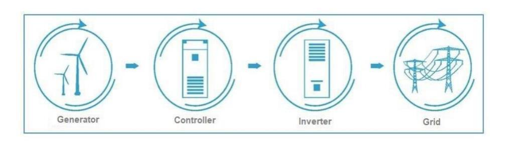
System connection diagram
Wind turbine generator system is composed of wind turbine generator, on-gridcontroller and on-grid inverter. (see the following photo)
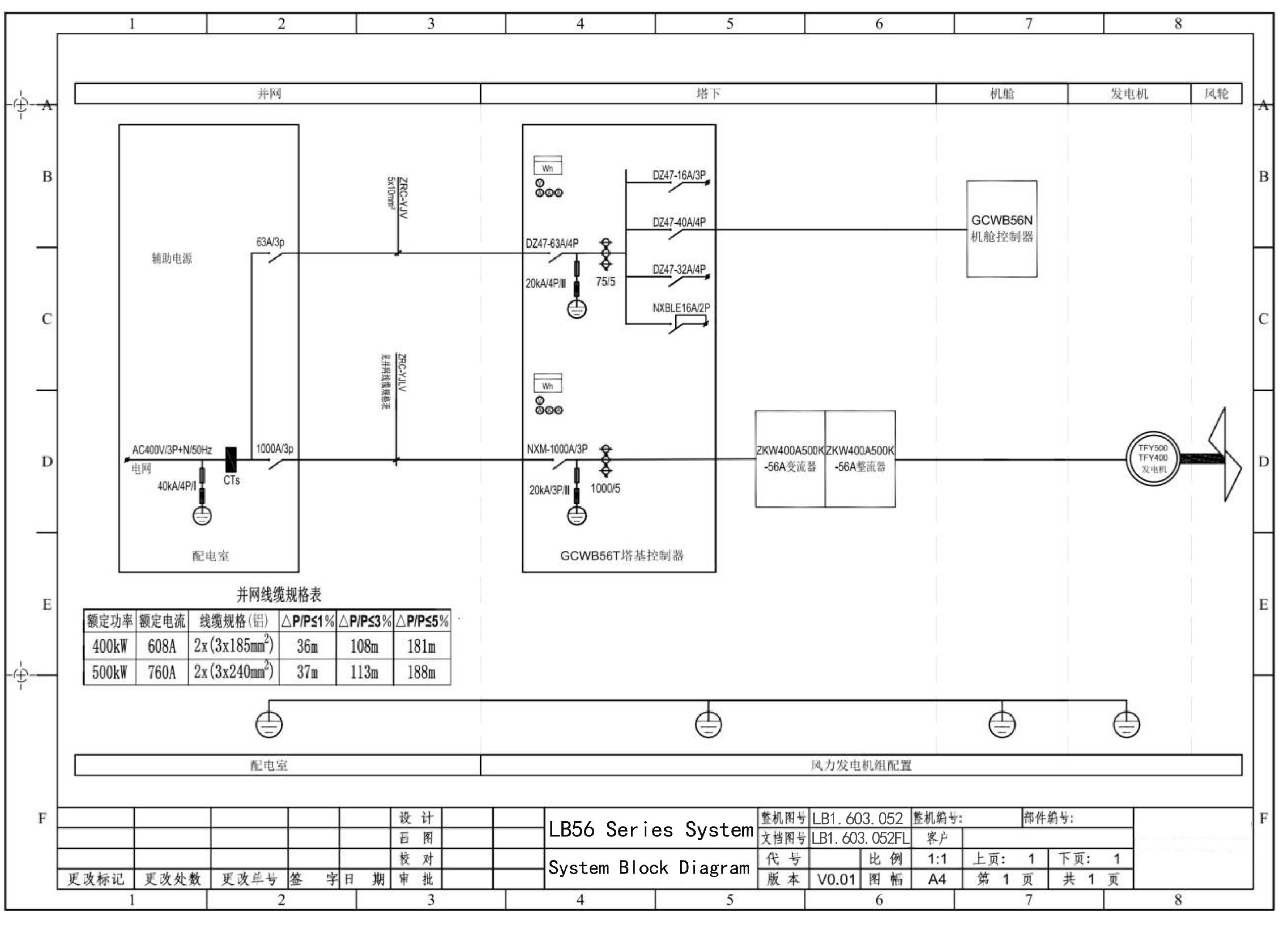
System electrical drawing
4. Performance
LB56-500 Power Curve
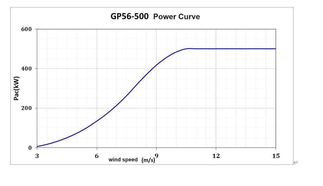
| wind speed(m/s) | 3.0 | 3.5 | 4.0 | 4.5 | 5.0 | 5.5 | 6.0 | 6.5 |
| power(kW) | 5.8 | 16.8 | 31.5 | 50.2 | 73.0 | 100.8 | 134.1 | 171.0 |
| wind speed(m/s) | 7.0 | 7.5 | 8.0 | 8.5 | 9.0 | 9.5 | 10.0 | 10.5 |
| power(kW) | 213.8 | 262.7 | 317.8 | 370.3 | 417.4 | 455.5 | 483.8 | 500.0 |
| wind speed(m/s) | 11.0 | 11.5 | 12.0 | 12.5 | 13.0 | 14.0 | 15.0 | ...... |
| power(kW) | 500.0 | 500.0 | 500.0 | 500.0 | 500.0 | 500.0 | 500.0 | ...... |
Usage instruction for power curve:
1. Data source: data source of power curve listed on the table is the result of calculationbased on the theoretical aerodynamic efficiency data of blades and efficiency of eachcomponent of wind turbine generator system, which is equivalent to the data under standardair density (1.225g/L).
2. Reference standard:lEC 61400-12-1,all data sources are 10-minute averages.
3. Application concern: when evaluating the site, power curve needs to be converted accordingto the actual air density of the site location. For related conversion methods, please refer toIEC 61400-12-1.
LB56-500 annual electric production
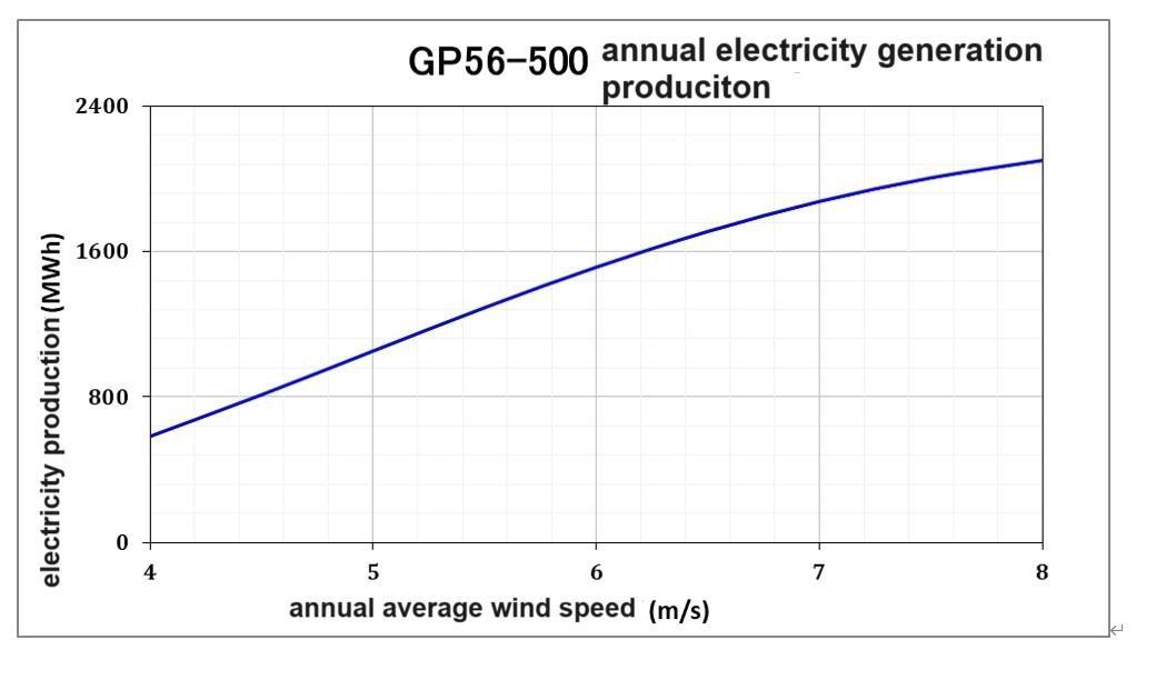
| annual average wind speed (m/s) | 4.0 | 4.5 | 5.0 | 5.5 | 6.0 | 6.5 | 7.0 |
| annual electricity production (MWh) | 583 | 812 | 1052 | 1291 | 1513 | 1709 | 1874 |
| annual electricity production (10MWh) | 58.3 | 81.2 | 105.2 | 129.1 | 151.3 | 170.9 | 187.4 |
| equivalent hours (h) | 1166 | 1623 | 105.2 | 2581 | 3026 | 3419 | 3748 |
Usage instructions for electricity generation:
1. Data source: the electricity generation is a theoretical value calculated according tocalculation method of lEC 61400-12-1 based on the above power curve
2. Reference standard: lEC 61400-12-1, assuming that the wind distribution is Rayleighdistribution.
3. Application concerns: actual electricity generation of WTG is related to factors such as sitetemperature, altitude, wind distribution, nearby obstacles, over-limit environment, and gridtransmission conditions.
LB56-400 power curve
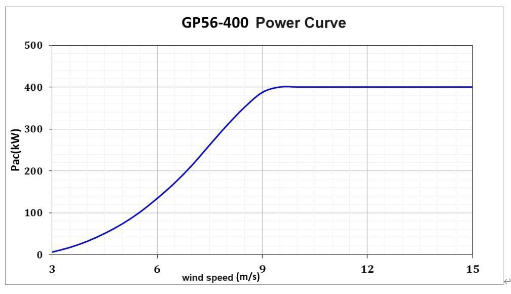
| wind speed(m/s) | 3.0 | 3.5 | 4.0 | 4.5 | 5.0 | 5.5 | 6.0 | 6.5 |
| power(kW) | 5.8 | 16.8 | 31.5 | 50.2 | 73.0 | 100.8 | 134.1 | 171.0 |
| wind speed(m/s) | 7.0 | 7.5 | 8.0 | 8.5 | 9.0 | 9.5 | 10.0 | 10.5 |
| power(kW) | 213.8 | 261.9 | 309.3 | 352.4 | 387.2 | 400.0 | 400.0 | 400.0 |
| wind speed(m/s) | 11.0 | 11.5 | 12.0 | 12.5 | 13.0 | 14.0 | 15.0 | ...... |
| power(kW) | 400.0 | 400.0 | 400.0 | 400.0 | 400.0 | 400.0 | 400.0 | ...... |
Usage instructions for power curve:
Data source: data source of power curve listed on the table is the result of calculation basedon the theoretical aerodynamic efficiency data of the blades and the efficiency ofeachcomponent, that is equivalent to the data under standard air density(1.225g/L).
Reference standard: lEC 61400-12-1, all data sources are 10-minute averages.
Application concern: when evaluating site, power curve needs to be converted according5to the actual air density at the site. For relevant conversion methods, please refer to lEC61400-12-1.
LB56-400 annual electric production
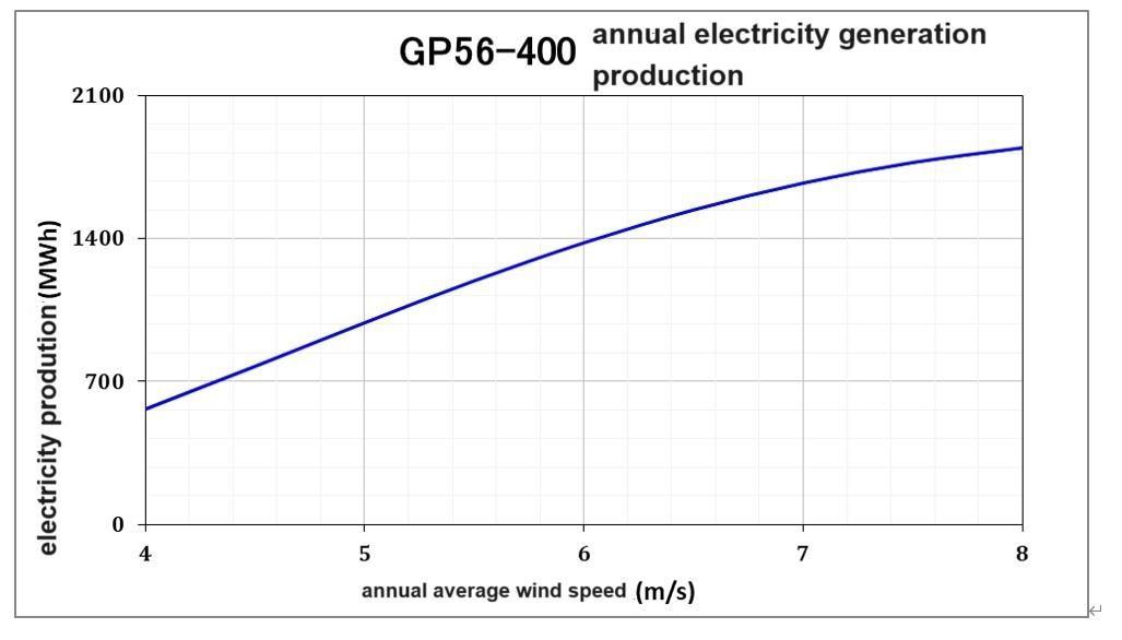
| annual average wind speed (m/s) | 4.0 | 4.5 | 5.0 | 5.5 | 6.0 | 6.5 | 7.0 |
| annual electricity production (MWh) | 567 | 776 | 989 | 1194 | 1379 | 1539 | 1670 |
| annual electricity production (10MWh) | 56.7 | 77.6 | 98.9 | 119.4 | 137.9 | 153.9 | 167.0 |
| equivalent hours (h) | 1417 | 1940 | 2473 | 2984 | 3448 | 3849 | 4176 |
Usage instructions for electricity generation production:
3. Data source: electricity generation production is a theoretical value calculated according tothe calculation method of lEC 61400-12-1 based on the above power curve.
4. Reference standard: lEC 61400-12-1, assuming that the wind distribution is Rayleighdistribution.
5. Application concerns: actual power generation production of WTG is related to factors such9as site temperature, altitude, wind distribution, nearby obstacles, over-limit environment. andgrid transmission conditions.
Thrust coefficient
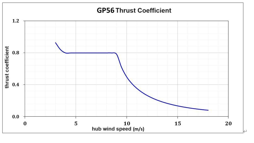
| Wind speed (m/s) | Thrust coefficient | Wind speed (m/s) | Thrust coefficient | Wind speed (m/s) | Thrust coefficient | Wind speed (m/s) | Thrust coefficient |
| 3.0 | 0.9270 | 7.0 | 0.7980 | 11.0 | 0.3534 | 15.0 | 0.1347 |
| 3.5 | 0.8387 | 7.5 | 0.7980 | 11.5 | 0.3049 | 15.5 | 0.1225 |
| 4.0 | 0.7978 | 8.0 | 0.7980 | 12.0 | 0.2656 | 16.0 | 0.1119 |
| 4.5 | 0.7979 | 8.5 | 0.7980 | 12.5 | 0.2335 | 16.5 | 0.1025 |
| 5.0 | 0.7979 | 9.0 | 0.7826 | 13.0 | 0.2068 | 17.0 | 0.0943 |
| 5.5 | 0.7980 | 9.5 | 0.6150 | 13.5 | 0.1843 | 17.5 | 0.0869 |
| 6.0 | 0.7979 | 10.0 | 0.4969 | 14.0 | 0.1652 | 18.0 | 0.0804 |
| 6.5 | 0.7980 | 10.5 | 0.4151 | 14.5 | 0.1488 |
Thrust coefficient illustration:
3. Data source: thrust coefficient is a theoretical value obtained by Bladed software based onWTG data simulation.
4. Reference standard: lEC61400-1, thrust coefficient is the steady-state operating value ofWTG.
5. Application concerns: actual thrust coefficient is related to factors such as s instantaneouswind speed, instantaneous rotational speed, pitch angle, blade surface roughness, andenvironment.
Electronic control system
Wind turbine generator control system includes the core control unit of wTG, pitch drivecontrol, yaw drive control, environmental monitoring, human-computer interaction, and powerconversion, that realizes automatic operation control of WTG and maximizes wind energy.Utilization and processing and recording of various events have the following characteristics,
1)Hardware stability & reliability: PLC-based distributed control system, using matureCANopen and EtherCAT buses for system connection.
2)software maturity& completeness: standard wind turbine code library and control strategywith superior performance in electricity generation effciency improvement and load control.
3)Pitch control fexibility: use different control strategies under different working conditionssuch as light wind start-up section, rated wind speed section, strong wind control section.wind speed over-limit, etc. to maximize the wind energy utilization and safe operation ofWTG.
4)Wind MPPT : combined with real-time air density and dynamically adjust the torque controlparameters to ensure MPPT of wind energy Cp.
5)Intelligent yawing strategy: intelligent untwisting and wind-direction strategies balancewind-direction accuracy and action frequency to improve wind-catching ability.
6)Comprehensive protection:complete wind turbine protection system with multi-levelprotection strategies to maximize utilization.
7)Load optimization control: flexibility control, tower resonance zone vibration isolation.strong wind speed suppression, pitch rate flexible adjustment, etc.
8)Intelligent monitoring & diagnosis: complete status code, protection logic and user rights8)management to maximize safety of WTG.
9)Efficient operation & maintenance troubleshooting: abundant operation, failure, operationlogs and failure recording records enable efficient operation & maintenancetroubleshooting.
10)Abundant environmental monitoring: WTG has various monitoring functions such as windspeed, wind direction, air pressure, temperature, humidity, vibration, etc.
11)Convenient monitoring & debugging: real-time data monitoring and display of wTG, andLoT operation screen realizes the simultaneous uploading of operating data to the cloud.
12) Simple power grid connection: using a converter that meets the grid standards, which canbe directly connected to the low-voltage 400V distribution network.
On-grid controller
| Control parameter | |
| Master controller | Industry PLC controller |
| Yawing speed | 0.55°/s |
| Yawing accuracy | ≤3.2° |
| Way of pitch | Three-blade independent pitch |
| Pitch speed | ≥8/s |
| Pitch accuracy | ≤0.2° |
| Pitch backup power | Super capacitor |
| Display &Communication | |
| Display panel | LCD |
| Communication interface | RS485、RJ45 internet access |
On-grid converter
| System model | LBGP56-500、LBGP56-400 |
| Generator side parameter | |
| Generator side working voltage range | 3 phase 200~460Vac |
| DC bus working volage range | 600V~ 720VDC |
| Brake unit configuration | Built-in control and dump-load resistors |
| Network side parameter | |
| Rated output power | 500kw、400kW |
| Rated grid voltage | 400V±15%3 phase 3 lines |
| Rated working frequency | 50/60Hz±5% |
| Power factor (PF) | >0.99 (0.85L~0.85C之间可调) |
| Maximum inverter efficiency | ≥97% |
| Harmonic content(THD) | Total current harmonics <5%,each time <3%(rated power) |
| Grid-tie protection function | Overvoltage,undervoltage,overfrequency,underfrequency,unbalance protection,etc. |
| Other grid-tie functions | Low voltage ride through, islanding protection |
6. Tower & Foundation
| Device model | LB56-500、LB56-400 |
| Tower model | TD162290-49 |
| Height | 49m |
| Section | 3 |
| Thickness | 10mm-14mm |
| Weight | 42t |
| Material | Q355ND |
| Flange diameter | 1620mm(upper)/2900mm(bottom) |
| Surface treatment | Painting |
| Base reference value | φ12mx1.6m(tower 49m) |
Foundation construction needs to go through start-up procedures, bring in machine tools andmaterials, excavation and leveling ofthe foundation pit, excavation of cable trenches and masonrymanholes, pre-embedding of ground rods and cushion formwork and pouring (C25), installationof foundation sections (crane 25 tons), the production and binding of embedded parts, formworkcutting and supporting, foundation pit pouring (C35), and foundation maintenance will take at least 20 days.

6.1 Overall appearance diagram
6.2 Upper foundation load
| Load case | Tower Mxy[kNm] | Tower Mz[kNm] | Tower Fxy[kN] | Tower Fz[kN] | Safety factor |
| Normal run load case | 4007 | 358 | 98 | -674 | 1.0 |
| Ultimate load case | 13646 | 245 | 318 | -924 | 1.35 |
6.3 Reference foundation

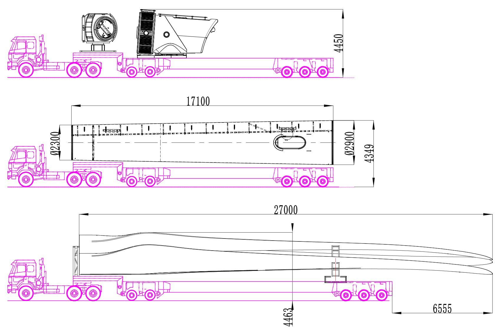
7. Wind turbine transportation
The main components of WTGS are listed and the loading diagram as follows:
| No. | Item | Weight (t) | Dimension (m) | Vehicle | Time |
| 1 | Ground cage & relatedaccessories | 2.5 | bulk packaging | ordinary vehicle | 1 |
| 2 | Nacelle & converter | 22.7 | 5.3m*3m*3.2m | 17.5m platfomm lorry | 1 |
| 3 | Hub | 5.5 | 2.4m*2.2m*2.2m | 1 | |
| 4 | Each section of tower(small parts assembly) | 15-22 | 22.5m*φ2.9 | 17.5m platfomm lorry | 1 |
| 5 | Blade | 7.5 | 27.5m*2.6m*2.8m |
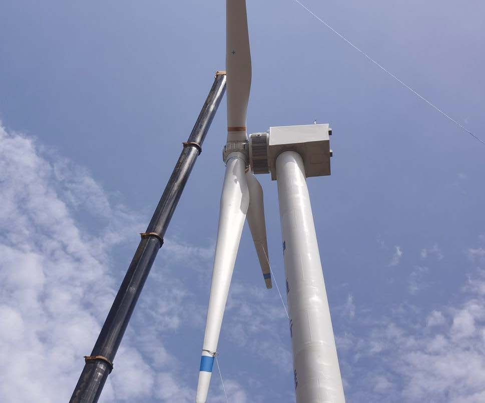
8. Hoisting request
In order to ensure the hoisting time, tower hoisting and wind rotor assembly are carried outsimultaneously. The requirements for the site are very strict. lt is necessary to ensure that there isspace for placement and installation of components. The flat area of the site should be wider tofacilitate the layout of hoisting installation. The tower needs to be placed in a flat area 20 meterslong and 10 meters wide, and the blades need to be placed in a flat area 50 meters long and 40meters wide for assembly of the wind wheel.
The road needs to ensure the passage of 17.5-meter flatbed vehicles. The turning radius isgreater than 20m. The geology must not be soft, otherwise it needs to be paved with sand andgravel.
The list of main tool requirements for each stage of hoisting is as follows:
| No. | Name | Specs | Qty | Time | Function |
| 1 | Crane | 75T | 1 pcs | 2 days | unloading & blade assembly |
| 2 | Crane | 260T | 1 pcs | 2 days | Tower & wind rotor assembly |
9. SCADA remote monitoring
Remote monitoring system CUBE3.0 with system functions & features:
• Data transmission: data connection and interaction can be carried out throughwired/wireless networks and access method is flexible and convenient.
• Real-time monitoring: log on the web page anytime & anywhere to observe and analyzereal-time operation status.
• Data logging: record various operation information, meteorological, grid data, electricitygeneration and other types of data.
• Report analysis: statistics of each monitoring quantity and fault records can be made by day,month and year and reports can be generated.
• Failure alarm: failure infomation can be notifed to operation and maintenance personnel ina timely manner by pre-classifying various types of failures.
• Operation & maintenance management: record each operation & maintenance informationand provide operation and maintenance status reminders according to maintenancerequirements.
• Safety and reliability: the server is built on a third-party cloud platform, which the networkservice is safe and reliable.
Related News
May 07,2025
Exploring the Durability of Color Steel Tile Roof Photovoltaic Brackets: A Comprehensive Guide

May 01,2025
Understanding Ground-Mounted Photovoltaic Power Stations: A Sustainable Energy Solution

Apr 27,2025
Ground Photovoltaic Station Supports: Key Factors for Optimal Performance

Tel / WhatsApp:
Tel / WhatsApp:
Follow Us

Online Consultation
Have questions or need more information?
SAF Coolest v1.3.1.2 设置面板 GAGSD-AGYF-JASZE-ZWV
https://dc.thefastmake.com/index.html?configure=--enable-dom-interceptor